本帖最后由 天工开发者团队 于 2024-10-28 17:15 编辑
一、扫描拉伸
概念:使用单一路径和横截面或多个路径和横截面创建扫描特征。
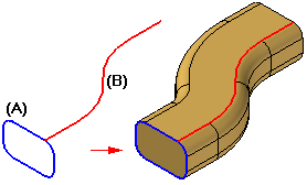

API:
- ModelPtr AddSweptProtrusion(
- long NumCurves,//指定在构建扫描凸出特征时使用的曲线对象的数量。
- const _variant_t& TraceCurves,//包含轮廓和/或边缘对象。数组的大小等于NumCurves的值。
- const _variant_t& TraceCurveTypes,//数组的大小等于NumCurves的值。包含FeaturePropertyConstants常量集合(igProfileBasedCrossSection, igEdgeBasedCrossSection)的成员,它们指定TraceCurves数组的相应成员是Profile对象还是Edge对象。
- long NumSections,//指定在构造扫描凸出特征时使用的Section对象的数量。
- const _variant_t& CrossSections,//包含轮廓和/或边缘对象。数组的大小等于NumSections的值
- const _variant_t& CrossSectionTypes,//数组的大小等于NumSections的值。
- const _variant_t& Origins,//包含定义相应截面的起始点的点。每个点表示为两个Double数组(例如,Dim dblOrigin(2) as Double;Dim Origins()作为Variant)。对于与周期性横截面(圆和椭圆)对应的此数组的成员,指定值为0,而不是指定表示点的数组。
- const _variant_t& SegmentMaps,
- enum FeaturePropertyConstants MaterialSide,
- enum FeaturePropertyConstants StartExtentType,
- double StartExtentDistance,
- IDispatch* StartSurfaceOrRefPlane,
- enum FeaturePropertyConstants EndExtentType,
- double EndExtentDistance,
- IDispatch* EndSurfaceOrRefPlane);
- template<typename T>
- _variant_t CreateVariant(T* t, VARENUM em)
- {
- // 暂时支持数量为一的一维数组
- SAFEARRAYBOUND bound = { 1, 0 };
- SAFEARRAY* pSafeArry = SafeArrayCreate(em, 1, &bound);
- SafeArrayPutElement(pSafeArry, &bound.lLbound, t);
- VARIANT var;
- VariantInit(&var);
- var.vt = VT_ARRAY | em;
- var.parray = pSafeArry;
- return _variant_t(var);
- }
- void AddSweptProtrusion()
- {
- Application* application = TGAddinApp::GetTGApp()->GetApplication();
- TGPart::PartDocumentPtr pDoc = application->GetActiveDocument();
- // 新建草图
- TGPart::SketchPtr pSketch = pDoc->Sketches->Add();
- //参考平面
- TGPart::RefPlanePtr pRefplane = pDoc->GetRefPlanes()->Item(1);
- // 轮廓
- TGPart::ProfilePtr pProfile = pSketch->GetProfiles()->Add(pRefplane);
- // 创建一个中线点为(0.0,0.0),长度为0.1,宽度为0.08的矩形
- TGFrameworkSupport::Lines2dPtr pLines2d = pProfile->GetLines2d();
- double cenX = 0.0, cenY = 0.0, width = 0.08, len = 0.1;
- std::array<TGFrameworkSupport::Line2dPtr, 4> lines;
- lines[0] = pLines2d->AddBy2Points(cenX - len / 2, cenY - width / 2, cenX + len / 2, cenY - width / 2);// 底边
- lines[1] = pLines2d->AddBy2Points(cenX + len / 2, cenY - width / 2, cenX + len / 2, cenY + width / 2); // 右边
- lines[2] = pLines2d->AddBy2Points(cenX + len / 2, cenY + width / 2, cenX - len / 2, cenY + width / 2); // 上边
- lines[3] = pLines2d->AddBy2Points(cenX - len / 2, cenY + width / 2, cenX - len / 2, cenY - width / 2); // 左边
- TGFrameworkSupport::Relations2dPtr pRelations2d = pProfile->GetRelations2d();
- for (int i = 0; i < 4; i++)
- {
- TGFrameworkSupport::Line2dPtr pLine = lines[i];
- TGFrameworkSupport::Line2dPtr pNextLine = lines[(i + 1) % 4];
- pRelations2d->AddKeypoint(
- pLine,
- (int)TGConstants::KeypointIndexConstants::igLineEnd,
- pNextLine,
- (int)TGConstants::KeypointIndexConstants::igLineStart,
- true);
- }
- pProfile->End(ProfileValidationType::igProfileClosed);
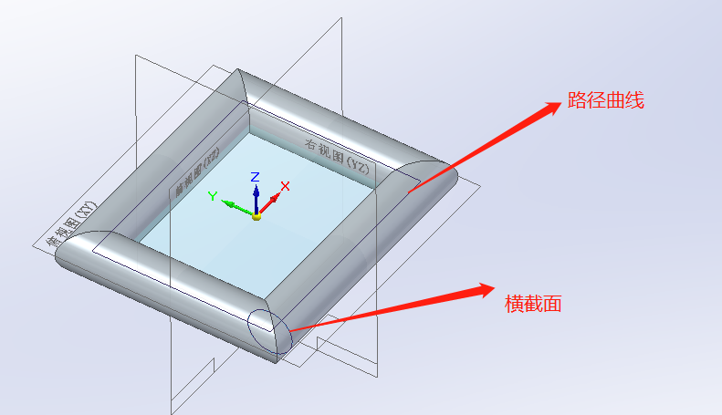
- // 将该矩形设置为路径曲线
- IDispatchPtr pTempTrace = static_cast<IDispatch*>(pProfile);
- _variant_t TraceCurves = CreateVariant<IDispatch>(pTempTrace, VT_DISPATCH);
- int TraceCurveType
- = TGConstants::FeaturePropertyConstants::igProfileBasedCrossSection;
- _variant_t TraceCurveTypes = CreateVariant<int>(&TraceCurveType, VT_INT);
- // 绘制截面轮廓
- _variant_t OrientationPlaneOrPivot(static_cast<IDispatch*>(pDoc->RefPlanes->Item(1)));
- _variant_t ParentCurve(static_cast<IDispatch*>(pProfile));
- pRefplane = pDoc->GetRefPlanes()->AddNormalToCurve(lines[0],
- ReferenceElementConstants::igCurveStart, OrientationPlaneOrPivot,
- ReferenceElementConstants::igPivotEnd, true, ParentCurve);
- pSketch = pDoc->Sketches->Add();
- ProfilePtr pProfileCross = pSketch->GetProfiles()->Add(pRefplane);
- // 绘制一个圆心为新平面(0.0,0.0),半径为0.001的圆
- pProfileCross->GetCircles2d()->AddByCenterRadius(0, 0.0, 0.01);
- auto status = pProfileCross->End(ProfileValidationType::igProfileClosed);
- // 将该圆设置为截面
- IDispatchPtr pTempCross = static_cast<IDispatch*>(pProfileCross);
- _variant_t CrossSections = CreateVariant<IDispatch>(pTempCross, VT_DISPATCH);
- int CrossSectionType
- = TGConstants::FeaturePropertyConstants::igProfileBasedCrossSection;
- _variant_t CrossSectionTypes = CreateVariant<int>(&CrossSectionType, VT_INT);
- // 截面原点,若截面为圆,此处为零
- int t = 0;
- _variant_t Origins = CreateVariant<int>(&t, VT_INT);
- // 以圆为截面,矩形为路径的扫掠添料的操作
- pDoc->Models->AddSweptProtrusion(
- 1,
- TraceCurves,
- TraceCurveTypes,
- 1,
- CrossSections,
- CrossSectionTypes,
- Origins,
- 0, //从此往下的参数都是预备参数,无需考虑
- FeaturePropertyConstants::igLeft,
- FeaturePropertyConstants::igNone,
- 0.0,
- NULL,
- FeaturePropertyConstants::igNone,
- 0.0,
- NULL
- );
- }

二、螺旋拉伸
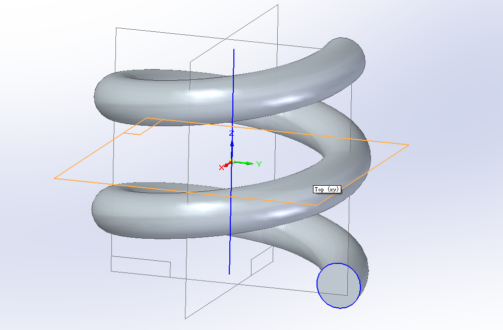
使用Models接口下的AddFiniteBaseHelix可创建螺旋特征:
- ModelPtr Models::AddFiniteBaseHelix(struct RefAxis* HelixAxis, enum FeaturePropertyConstants AxisStart,
- long NumCrossSections, SAFEARRAY** CrossSectionArray, enum FeaturePropertyConstants ProfileSide,
- double Height, double Pitch, double NumberOfTurns, enum FeaturePropertyConstants HelixDir,
- const _variant_t& TaperAngle = vtMissing, const _variant_t& TaperSide = vtMissing,
- const _variant_t& EndPitch = vtMissing, const _variant_t& DeltaPitch = vtMissing,
- const _variant_t& TaperStartRadius = vtMissing, const _variant_t& TaperEndRadius = vtMissing,
- const _variant_t& FromFaceOrRefPlane = vtMissing, const _variant_t& ToFaceOrRefPlane = vtMissing);
- void AddHelixProtrusion()
- {
- namespace pt = TGPart;
- namespace fwp = TGFrameworkSupport;
- pt::PartDocumentPtr pPartDoc = SEAPP->GetActiveDocument();
- pt::RefPlanePtr pRefPlaen = pPartDoc->GetRefPlanes()->Item(2l);
- pt::ProfilePtr pProfile = pPartDoc->GetProfileSets()->Add()->GetProfiles()->Add(pRefPlaen);
- fwp::Line2dPtr pLine = pProfile->GetLines2d()->AddBy2Points(0, -0.05, 0, 0.05);
- pt::RefAxisPtr pRefAxis = pProfile->SetAxisOfRevolution(pLine);
- fwp::Circle2dPtr pCrossSection = pProfile->GetCircles2d()->AddByCenterRadius(0.05, -0.05, 0.01);
- ATL::CComSafeArray<IDispatch*> crossSectionArray(1);
- crossSectionArray[0] = pProfile;
- pPartDoc->GetModels()->AddFiniteBaseHelix(pRefAxis, // 螺旋轴
- pt::igStart, // pt::igStart表示从轴定义的线段起点向终点向螺旋,pt::igEnd表示从轴定义的线段终点向起点螺旋
- 1, crossSectionArray.GetSafeArrayPtr(), // 传入横截面
- pt::igRight, // 为未来开放路径预留,暂时无用,pt::igRight和pt::igLeft为有效值
- 0.1, // 螺高,暂时无用
- 0.05, // 螺距
- 2, // 螺数
- pt::igRight // pt::igRight右旋,pt::igLeft左旋
- );
- }

三、法向拉伸
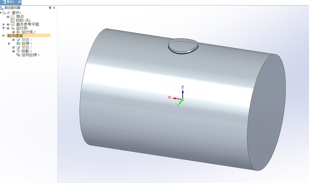
概念:法向拉伸通过拉伸位于零件面上的封闭曲线构造垂直于该面的拉伸,适用于使用文本轮廓或其他草图元素在非平整面构建特征时。与普通拉伸不同,法向拉伸命令并不基于轮廓。要构造法向拉伸特征,有几个前提:
一、已有一个设计模型
二、已将一个草图或草图中的某些轮廓投影至设计模型中。
使用下述Api可以创建一个法向拉伸特征。
- NormalToFaceProtrusions::Add(
- long NumberOfInputCurves,// 传入的edges个数
- const _variant_t& InputCurvesSetArray, // edges
- enum FeaturePropertyConstants LongestCurveSide, // pt::igLeft 向外拉伸(加料) pt::igRight 向内拉伸(除料)
- double offsetDistance, // 拉伸厚度
- enum FeaturePropertyConstants FaceContainment// pt::igFacesTouchingCurvesOnly 仅修改与曲线接触的面
- // pt::igAllFaces 修改曲线图内的所有面
- );
- void AddNormalProtrusion()
- {
- namespace pt = TGPart;
- namespace gm = TGGeometry;
- pt::PartDocumentPtr pPartDoc = SEAPP->GetActiveDocument();
- assert(pPartDoc);
- // 首先创建一个圆柱
- pt::RefPlanePtr pYOZPlane = pPartDoc->GetRefPlanes()->Item(2l);
- pt::ProfilePtr pProfile = pPartDoc->GetSketches()->AddByPlane(pYOZPlane)->GetProfile();
- pProfile->GetCircles2d()->AddByCenterRadius(0.0, 0.0, 0.2);
- ATL::CComSafeArray<IDispatch*> aProfiles(1);
- aProfiles.SetAt(0, pProfile);
- pt::ModelPtr pCylinderModel = pPartDoc->GetModels()->AddFiniteExtrudedProtrusion(1, aProfiles.GetSafeArrayPtr(),
- pt::igSymmetric, 0.6);
- // 在一个新的草图上创建一个圆
- pt::RefPlanePtr pXOYPlane = pPartDoc->GetRefPlanes()->Item(1l);
- pt::SketchPtr pSketch = pPartDoc->GetSketches()->AddByPlane(pXOYPlane);
- pt::ProfilePtr pProfileScd = pSketch->GetProfile();
- pProfileScd->GetCircles2d()->AddByCenterRadius(0.0, 0.0, 0.05);
- // 投影圆所在草图到圆柱面上
- gm::BodyPtr pBody = pCylinderModel->GetBody();
- gm::FacesPtr pFaces = pBody->GetFaces(gm::igQueryCylinder);
- assert(pFaces->GetCount() > 0);
- gm::FacePtr pFace = pFaces->Item(1l);
- long faceCnt = pFaces->GetCount();
- pt::ProjectCurvesPtr pProjCvs = pPartDoc->GetConstructions()->GetProjectCurves();
- pt::RefPlanePtr pDestPlane = pPartDoc->GetRefPlanes()->AddParallelByDistance(pXOYPlane, 0.2, pt::igNormalSide);
- pt::ProjectCurvePtr pProjCv = pProjCvs->Add(pSketch, pFace, pDestPlane, pt::igRight, pt::igProjectOptionProject);
- // 法向拉伸
- gm::EdgesPtr pProjEdges = pProjCv->GetEdges(gm::igQueryAll);
- long projEdgeCnt = pProjEdges->GetCount();
- ATL::CComSafeArray<IDispatch*> aEdges(projEdgeCnt);
- for (long i = 0; i < projEdgeCnt; i++)
- {
- aEdges.SetAt(i, pProjEdges->Item(i + 1));
- }
- _variant_t varEdges;
- varEdges.parray = aEdges.Detach();
- varEdges.vt = VT_ARRAY | VT_DISPATCH;
- pCylinderModel->GetNormalToFaceProtrusions()->Add(projEdgeCnt, // 传入的edges个数
- varEdges, // edges
- pt::igLeft, // pt::igLeft 向外拉伸(加料) pt::igRight 向内拉伸(除料)
- 0.01, // 拉伸厚度
- pt::igFacesTouchingCurvesOnly // pt::igFacesTouchingCurvesOnly 仅修改与曲线接触的面
- // pt::igAllFaces 修改曲线图内的所有面
- );
- }

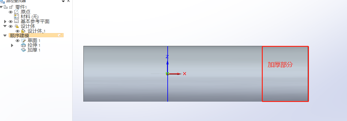
四、加厚
加厚命令通过偏移一个或多个面来加厚零件,SDK中使用Thickens::Add方法用于加厚。
其原型为:
- ThickenPtr Add(
- enum FeaturePropertyConstants Side, //加厚方法
- double offsetDistance, // 加厚厚度
- long NumberOfFaces, // 要加厚的面的个数
- SAFEARRAY** Faces // 要加厚的面集
- )
- // 添加加厚特征
- void AddThickenFeature()
- {
- namespace pt = TGPart;
- namespace gm = TGGeometry;
- pt::PartDocumentPtr pPartDoc = SEAPP->GetActiveDocument();
- assert(pPartDoc);
- // 使用对称拉伸,创建一个圆柱,圆柱顶底面法向分别为左、右视图
- // 圆柱底面半径0.1,圆柱高0.6
- pt::RefPlanePtr pYOZPlane = pPartDoc->GetRefPlanes()->Item(2l);
- pt::ProfilePtr pProfile = pPartDoc->GetSketches()->AddByPlane(pYOZPlane)->GetProfile();
- pProfile->GetCircles2d()->AddByCenterRadius(0.0, 0.0, 0.1);
- ATL::CComSafeArray<IDispatch*> aProfiles(1);
- aProfiles.SetAt(0, pProfile);
- pt::ModelPtr pCylinderModel = pPartDoc->GetModels()->AddFiniteExtrudedProtrusion(1, aProfiles.GetSafeArrayPtr(),
- pt::igSymmetric, 0.6);
- // 加厚顶、底面其中之一,使不对称
- gm::BodyPtr pBody = pCylinderModel->GetBody();
- gm::FacesPtr pFaces = pBody->GetFaces(gm::igQueryPlane);
- assert(pFaces->GetCount() == 2);
- ATL::CComSafeArray<IDispatch*> aFaces(1);
- aFaces.SetAt(0, pFaces->Item(1l));
- // 朝外侧加厚0.2
- pCylinderModel->GetThickens()->Add(pt::igRight, // 加厚方向 一般为igRight(外侧),
- // 对于单个的曲面特征可以往两侧加厚,则可为igLeft 或 igBoth(未验证)
- 0.2, // 加厚厚度
- 1l, aFaces.GetSafeArrayPtr() // 模型中要加厚的面
- );
- }

五、实体拉伸
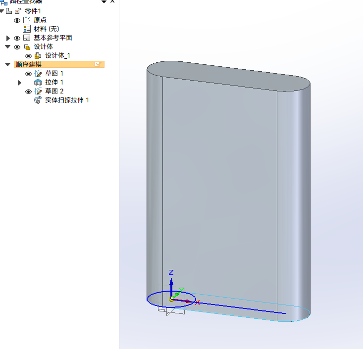
使用SolidSweptProtrusions::Add方法可以基于已知实体和扫掠路径添加实体扫掠特征,这个方法的原型为:
- SolidSweptProtrusionPtr Add(IDispatch* pTargetBody, //目标实体 要求为gm::Body
- IDispatch* pToolBody, // 原始实体 要求为gm::Body 可与pTargetBody相等
- IDispatch* pPath, // 扫掠路径,要求为pt::Profile
- IDispatch* pRotationAxis, // 原始实体的旋转轴,对于圆柱、圆锥体,可传nullptr
- IDispatch* pLockDirection,
- VARIANT_BOOL bToolOnPath, // true时,在路径上旋转工具体;false时,垂直于曲面放置工具
- VARIANT_BOOL bProtrusion // true时,拉伸;false时,除料
- );
- void AddSolidSweptExtruProtrusion()
- {
- namespace pt = TGPart;
- namespace fwp = TGFrameworkSupport;
- namespace gm = TGGeometry;
- pt::PartDocumentPtr pPartDoc = SEAPP->GetActiveDocument();
- assert(pPartDoc);
- // 创建一个圆柱体用于演示
- pt::ProfilePtr pProfile = pPartDoc->GetSketches()->AddByPlane(pPartDoc->GetRefPlanes()->Item(1l))->GetProfile();
- pProfile->GetCircles2d()->AddByCenterRadius(0, 0, 0.1); // 中心位于原点,半径0.1
- ATL::CComSafeArray<IDispatch*> aProfiles(1);
- aProfiles.SetAt(0, pProfile);
- pt::ModelPtr pModelFst = pPartDoc->GetModels()->AddFiniteExtrudedProtrusion(aProfiles.GetCount(), aProfiles.GetSafeArrayPtr(), pt::igRight, 1.0);
- // 创建扫掠路径(一条直线)
- pt::RefPlanePtr pXOYPlane = pPartDoc->GetRefPlanes()->Item(1l);
- pt::ProfilePtr pXOYProfile = pPartDoc->GetSketches()->AddByPlane(pPartDoc->GetRefPlanes()->Item(1l))->GetProfile();
- fwp::Line2dPtr pLine2d = pXOYProfile->GetLines2d()->AddBy2Points(0, 0, 0.5, 0);
- // 进行实体扫掠
- pt::SolidSweptProtrusionsPtr pSweptProtrusions = pModelFst->GetSolidSweptProtrusions();
- assert(pModelFst->GetExtrudedProtrusions()->GetCount() > 0);
- pt::ExtrudedProtrusionPtr pCylinder = pModelFst->GetExtrudedProtrusions()->Item(1l);
- gm::BodyPtr pToolBody = pModelFst->GetBody();
- gm::BodyPtr pTargetBody = pToolBody;
- pt::SolidSweptProtrusionPtr pBodySwept = pSweptProtrusions->Add(pTargetBody, pToolBody,
- pXOYProfile, nullptr, nullptr, VARIANT_TRUE, VARIANT_TRUE);
- }
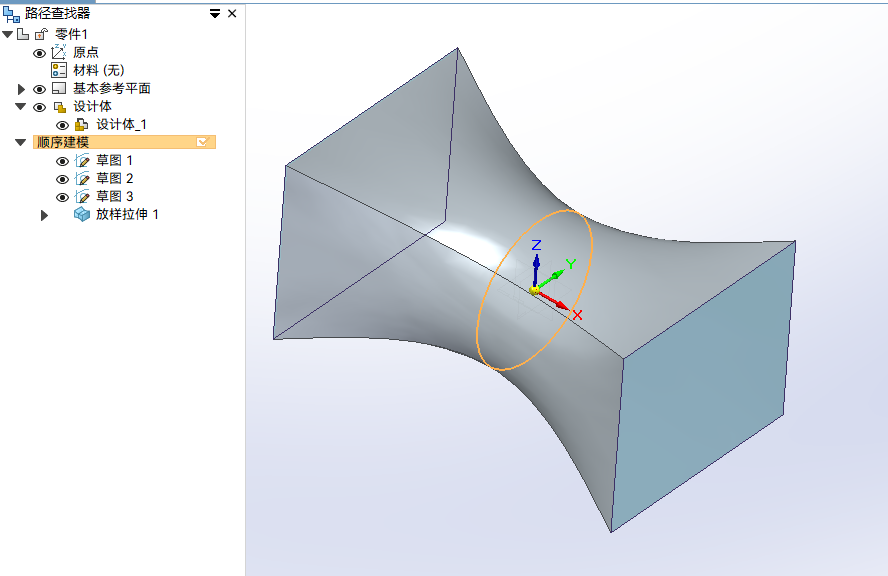
六、放样拉伸
放样拉伸操作通过连接一系列闭合截面形成三维模型,可以使用Models::AddLoftedProtrusion方法进行放样拉伸。
- template<typename T>
- ATL::CComSafeArray<T> ToComSafeArray(std::initializer_list<T> const& initial_list)
- {
- ATL::CComSafeArray<T> comArray((ULONG)initial_list.size());
- long i = 0;
- for (auto it = initial_list.begin(); it != initial_list.end(); ++it)
- {
- comArray.SetAt(i, *it);
- i++;
- }
- return comArray;
- }
- template<typename T>
- _variant_t ToArrayVar(std::initializer_list<T> const& initial_list)
- {
- VARENUM varEnum;
- if (std::is_same_v<T, double>)
- {
- varEnum = VT_R8;
- }
- else if (std::is_same_v<T, int>)
- {
- varEnum = VT_I4;
- } else if (std::is_same_v<T, float>)
- {
- varEnum = VT_R4;
- }
- else if (std::is_same_v<T, IDispatch*>)
- {
- varEnum = VT_DISPATCH;
- }
- else if (std::is_same_v<T, long>)
- {
- varEnum = VT_I8;
- }
- else
- {
- static_assert("未定义的类型");
- }
- ATL::CComSafeArray<T> comArray = ToComSafeArray(initial_list);
- _variant_t var;
- var.vt = VT_ARRAY| varEnum;
- var.parray = comArray.Detach();
- return var;
- }
- _variant_t ToEmbedVar(std::initializer_list<_variant_t> const& initial_list)
- {
- SAFEARRAYBOUND arrBound{ initial_list.size(),0};
- SAFEARRAY* psa = SafeArrayCreate(VT_VARIANT, 1, &arrBound);
- long i = 0;
- for (auto it = initial_list.begin(); it != initial_list.end(); ++it,++i)
- {
- SafeArrayPutElement(psa, &i, (void*)(&(*it)));
- }
- _variant_t var;
- var.vt = VT_ARRAY | VT_VARIANT;
- var.parray = psa;
- return var;
- }
- void CreateRectange(TGPart::ProfilePtr pProfile, double cenX, double cenY, double len, double width)
- {
- namespace fwp = TGFrameworkSupport;
- // 矩形在天工CAD中由四条首尾相连的直线组成
- fwp::Lines2dPtr pLines2d = pProfile->GetLines2d();
- std::array<fwp::Line2dPtr, 4> lines;
- lines[0] = pLines2d->AddBy2Points(cenX - len / 2, cenY - width / 2, cenX + len / 2, cenY - width / 2);// 底边
- lines[1] = pLines2d->AddBy2Points(cenX + len / 2, cenY - width / 2, cenX + len / 2, cenY + width / 2); // 右边
- lines[2] = pLines2d->AddBy2Points(cenX + len / 2, cenY + width / 2, cenX - len / 2, cenY + width / 2); // 上边
- lines[3] = pLines2d->AddBy2Points(cenX - len / 2, cenY + width / 2, cenX - len / 2, cenY - width / 2); // 左边
- fwp::Relations2dPtr pRelations2d = pProfile->GetRelations2d();
- for (int i = 0; i < 3; i++)
- {
- fwp::Line2dPtr pLine = lines[i];
- fwp::Line2dPtr pNextLine = lines[(i + 1) % 4];
- pRelations2d->AddKeypoint(
- pLine,
- (int)TGConstants::KeypointIndexConstants::igLineEnd,
- pNextLine,
- (int)TGConstants::KeypointIndexConstants::igLineStart,
- true);
- }
- pProfile->End(TGPart::ProfileValidationType::igProfileClosed);
- }
- void AddLoftProtrusion()
- {
- namespace pt = TGPart;
- namespace fwp = TGFrameworkSupport;
- pt::PartDocumentPtr pPartDoc = SEAPP->GetActiveDocument();
- pt::RefPlanePtr pSidePlane = pPartDoc->GetRefPlanes()->Item(2l); // 侧平面
- // 左剖面,画一个矩形
- pt::RefPlanePtr pFstPlane = pPartDoc->GetRefPlanes()->AddParallelByDistance(pSidePlane, 0.5, pt::igReverseNormalSide);
- pt::ProfilePtr pFstProfile = pPartDoc->GetSketches()->AddByPlane(pFstPlane)->GetProfile();
- CreateRectange(pFstProfile, 0, 0, 0.6, 0.5);
- // 中间剖面,画一个圆
- pt::ProfilePtr pScdProfile = pPartDoc->GetSketches()->AddByPlane(pSidePlane)->GetProfile();
- pScdProfile->GetCircles2d()->AddByCenterRadius(0, 0, 0.2);
- // 右剖面,画一个矩形
- pt::RefPlanePtr pTrdPlane = pPartDoc->GetRefPlanes()->AddParallelByDistance(pSidePlane, 0.5, pt::igNormalSide);
- pt::SketchsPtr pSketchs = pPartDoc->GetSketches();
- pt::SketchPtr pSketch = pPartDoc->GetSketches()->AddByPlane(pTrdPlane);
- pt::ProfilePtr pTrdProfile = pSketch->GetProfile();
- CreateRectange(pTrdProfile, 0, 0, 0.6, 0.5);
- // 创建放样拉伸特征
- _variant_t sectionArr = ToArrayVar({
- (IDispatch*)pFstProfile.GetInterfacePtr(),(IDispatch*)pScdProfile.GetInterfacePtr(),
- (IDispatch*)pTrdProfile.GetInterfacePtr(),});
- _variant_t sectTypeArr = ToArrayVar({
- (int)pt::igProfileBasedCrossSection,
- (int)pt::igProfileBasedCrossSection,
- (int)pt::igProfileBasedCrossSection});
- _variant_t sectionFstStPoints = ToArrayVar({ -0.3,-0.25 });
- _variant_t sectionTrdStPoints = ToArrayVar({ -0.3,-0.25 });
- _variant_t orginArr = ToEmbedVar({ sectionFstStPoints,_variant_t(0),sectionTrdStPoints });
- pt::ModelsPtr pModels = pPartDoc->GetModels();
- pModels->AddLoftedProtrusion(3, sectionArr, sectTypeArr, orginArr, 0, pt::igLeft,
- pt::igNone, 0.0, nullptr, pt::igNone, 0.0, nullptr, pt::igNone, 0.0, pt::igNone, 0.0);
- }
AddLoftedProtrusion的原型为:
- ModelPtr AddLoftedProtrusion (
- long NumSections,const _variant_t & CrossSections,const _variant_t & CrossSectionTypes,
- const _variant_t & Origins,const _variant_t & SegmentMaps,enum FeaturePropertyConstants MaterialSide,
- enum FeaturePropertyConstants StartExtentType,double StartExtentDistance,IDispatch * StartSurfaceOrRefPlane,
- enum FeaturePropertyConstants EndExtentType,double EndExtentDistance,IDispatch * EndSurfaceOrRefPlane,
- enum FeaturePropertyConstants StartTangentType,double StartTangentMagnitude,enum FeaturePropertyConstants EndTangentType,
- double EndTangentMagnitude,const _variant_t & NumGuideCurves = vtMissing,
- const _variant_t & GuideCurves = vtMissing );
虽然它看起来参数众多,但是一般只需要关注前四个参数,后面的参数要么是预留的,要么暂时是固定项。
NumSections 截面个数
CrossSections 用于传入截面,VT_ARRAY|VT_DISPATCH类型的变体,要求其内Dispatch个数和截面个数相同
CrossSectionTypes 用于传入截面类型,VT_ARRAY|VT_I4型的变体,要求数组元素个数与截面个数相同,每个都用于描述CrossSections对应的截面类型
Origins 用于描述每个截面的起始点,这些起始点集影响拉伸效果。VT_ARRAY|VT_VARIANT类型的变体,要求数组元素个数与截面个数相同。如果是周期性的截面(如圆、椭圆),作为元素的变体可以只传0。否则作为元素的变体是VT_ARRAY|VT_R8类型的数组,元素个数为2。
|
![]() 增值电信业务经营许可证 合字B2-20230386
增值电信业务经营许可证 合字B2-20230386![]() 沪公网安备31011202020614 Powered by Discuz! X3.5
沪公网安备31011202020614 Powered by Discuz! X3.5